Introduction
A radiator is only as reliable as the process that built it. For heavy equipment operators running Caterpillar dozers, Komatsu excavators, or Freightliner commercial trucks, a cooling failure doesn't just mean a repair bill — it means unplanned downtime, lost productivity, and potentially a damaged engine.
The radiator assembly process transforms raw aluminum tubes, fins, tanks, and brazing alloys into a pressure-rated heat exchanger built to handle extreme thermal loads. Knowing how that process works helps you evaluate replacement units, source parts confidently, and diagnose why a recently installed radiator failed ahead of schedule.
This guide covers every stage — from raw material preparation through final pressure testing — with specific focus on the tolerances and failure modes that matter most in construction, mining, and agricultural applications.
Key Takeaways
- Radiator assembly runs through five core stages: material preparation, core matrix assembly, brazing, tank attachment, and final inspection
- Controlled atmosphere brazing (CAB) is the most critical stage; process deviations produce joint failures undetectable without pressure testing
- Heavy equipment radiators require tighter tolerances than passenger vehicle units due to higher heat loads, longer duty cycles, and constant vibration
- External appearance is not a reliable indicator of internal assembly quality — testing documentation matters
- Aftermarket replacements should be verified for assembly standards and testing protocols before purchasing
What Is the Radiator Assembly Process?
The radiator assembly process is the complete fabrication sequence that takes individual components — tubes, fins, header tanks, gaskets, and mounting hardware — and joins them into a single, pressure-rated heat exchanger. This is distinct from radiator installation (fitting a finished unit into a machine) or radiator repair (restoring a failed unit already in service).
The intended outcome is a structurally sound, leak-free assembly that sustains continuous coolant flow, withstands operating pressure, and dissipates engine heat consistently over thousands of service hours.
Achieving those performance targets starts with material selection. Modern radiator cores are built primarily from aluminum alloys — Granges' heat exchanger materials catalog (a widely referenced industry resource) documents the breakdown by function: 3xxx-series aluminum for core and fin structures, 4xxx-series alloys as brazing layers, and proprietary corrosion-resistant alloys for applications with aggressive coolant chemistry or higher fatigue demands.
That sequence plays out across five distinct stages, each with defined tolerances that shift depending on the application:
- Material preparation — cutting and forming tubes, fins, and header components to spec
- Core stacking — aligning fins and tubes into the core matrix
- Brazing — bonding the assembly under controlled heat
- Tank attachment — joining header tanks to the brazed core
- Leak testing — pressure-verifying the completed unit before release
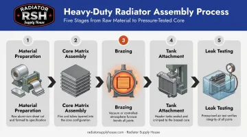
These stages apply across heavy equipment, commercial truck, and industrial radiator manufacturing, though testing thresholds and dimensional tolerances vary by application.
Why the Radiator Assembly Process Matters for Heavy Equipment
Demands That Passenger Car Standards Don't Cover
Heavy equipment radiators operate in conditions that push far beyond what passenger vehicle cooling systems face:
- Greater sustained heat rejection from higher continuous engine output
- Longer duty cycles: John Deere reports customers average 400 hours annually in a combine, and construction and mining equipment often runs harder
- Constant vibration from ground engagement, rough terrain, and drivetrain loads
- Extreme ambient temperatures in open-pit mining, desert construction, and harvest operations
These conditions make manufacturing precision directly tied to field reliability. A 2020 truck radiator fatigue study found that robust design geometry produced five times the pressure-cycle life compared to a nominal design — a difference driven entirely by how the assembly was engineered and built.
What Compromised Assembly Quality Produces
When manufacturing shortcuts occur at any stage, the failure modes are predictable:
- Tube-to-header micro-leaks from incomplete brazing at joint contact points
- Fin separation that reduces effective heat transfer area and cooling capacity under load
- Tank delamination or seam failures under sustained pressure and thermal cycling
- Flux residue blockages that partially obstruct coolant channels, cutting flow rate with no visible external sign of damage
These aren't catastrophic failures at startup. They're progressive degradation issues that appear after hours of heavy operation — exactly when downtime is most costly.
Sourcing Implications
Knowing what drives these failures makes it easier to ask the right questions when evaluating aftermarket suppliers. Radiator Supply House's ICEBOX Replacement parts are manufactured to OEM specifications, covering 300+ manufacturers including Caterpillar, Komatsu, and Freightliner. For select applications where OEM designs specified plastic tanks — such as the Komatsu PC228 series — ICEBOX uses metal construction instead. Plastic tanks on high-cycle equipment are prone to seam fatigue and pressure-related cracking; the metal upgrade directly eliminates that failure path.
How the Radiator Assembly Process Works
Step 1: Material Preparation — Tubes and Fins
Aluminum tubes are formed through precision rolling or extrusion to create the channels that carry coolant through the core. Fins are stamped from thin aluminum sheet stock, shaped to maximize surface area exposed to airflow.
Material selection at this stage determines corrosion resistance, thermal conductivity, and fatigue life. The brazing alloys used are application-specific: Solvay documents AA4343 (liquidus 613°C) and AA4045 (liquidus 591°C) as common filler alloys for aluminum heat exchangers, clad onto tube surfaces before assembly.
Alloy selection varies by manufacturer and application — there is no single universal industry standard.
Dimensional tolerances at this stage — tube wall thickness, fin pitch, fin height — directly govern the assembled unit's thermal performance. These specifications are not publicly standardized across the heavy-duty market; they're application-specific dimensions validated against required heat rejection for each equipment model.
Step 2: Core Matrix Assembly
Tubes and fins are stacked in a precise pattern to form the heat exchanger matrix. Fins sit between tubes, creating the large surface area that transfers heat from the coolant to passing air.
Key design variables set at this stage include:
- Number of tube rows (depth of the core)
- Fin density measured in fins per inch (FPI)
- Tube spacing and alignment
Each variable is engineered against specific heat rejection requirements and airflow conditions for the machine in question. SAE J1994 provides the laboratory framework for measuring heat transfer and pressure drop performance, while SAE J1393 covers complete heavy-duty cooling system performance testing.
Alignment errors or inconsistent fin spacing at this stage compromise both structural integrity and heat transfer efficiency in the finished unit. These defects are difficult to detect without performance testing.
Step 3: Brazing in a Controlled Atmosphere Furnace
Controlled atmosphere brazing (CAB) is where the core matrix becomes a permanent, unified structure. The assembled core is coated with flux, dried at approximately 200°C, then loaded into a nitrogen-atmosphere furnace that melts the brazing alloy at every tube-to-fin contact point simultaneously — without melting the base aluminum.
The process control parameters from Solvay's documented CAB process are specific:
| Parameter | Specification |
|---|---|
| Furnace atmosphere | Nitrogen; oxygen below 100 ppm |
| Dew point | At or below -40°C |
| Flux type | Potassium fluoroaluminate (K₁₋₃AlF₄₋₆) |
| Flux application rate | Approximately 5 g/m² |
| Flux melting interval | 565–572°C |
| AA4045 brazing range | 588–604°C |
| AA4343 brazing range | 593–621°C |
| Drying temperature | ~200°C (above 250°C creates oxides flux cannot remove) |
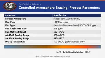
Deviation from any of these parameters produces voids or unbrazed areas at joint contact points. These defects are invisible to visual inspection but fail under thermal cycling or vibration in service.
Magnesium content above approximately 0.5% in the base alloy can also impair flux performance — which is why alloy selection at Step 1 carries direct consequences here.
Step 4: Tank and Header Attachment
After brazing, header tanks are attached to each end of the core. The attachment method — crimped, welded, or mechanically fastened — depends on tank material and application requirements.
For heavy equipment:
- All-aluminum welded tanks are common in construction, mining, and high-demand agricultural applications, as welded joints handle sustained vibration and pressure cycling more reliably
- Reinforced plastic tanks (crimped with rubber gaskets) are widely used in on-highway commercial vehicles and some agricultural equipment, though they carry greater risk of cracking under the pressure cycles and vibration frequencies of off-highway work
Rubber gaskets seal the tank-to-core joint under operating pressure. Gasket condition and seating quality at assembly are the primary determinants of whether this joint holds over thousands of operating hours.
The Freightliner 108SD illustrates how tank design can drive installation complexity: its internal transmission oil cooler integration requires specific sequencing — removing both oil cooler lines simultaneously can allow the cooler to shift position inside the tank, causing a coolant leak later in service.
Step 5: Final Inspection and Pressure Testing
No radiator should leave a manufacturing facility without documented leak testing. Production methods include:
- Pressure-decay testing — measures pressure drop over time to identify leaks
- Water-bath/bubble testing — submerged unit under air pressure; bubbles indicate leaks
- Helium tracer-gas testing — helium vacuum leak detection can reach approximately 10⁻⁸ mbar·l/s sensitivity, far below what bubble testing can detect
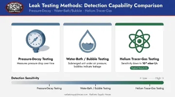
Premium units also undergo thermal cycle testing and flow rate verification. SAE J1597 covers pressure-cycle durability testing for vehicle and industrial heat exchangers, though its public scope does not establish a single universal acceptance pressure — test thresholds are application-specific.
After testing, packaging is engineered to protect fin surfaces during transit. Fin damage in shipping reduces effective heat transfer area before the unit is ever installed.
Key Factors That Affect Radiator Assembly Quality
In heavy-duty applications, assembly quality separates radiators that last through full service cycles from those that fail under load. Five variables determine where a unit falls on that spectrum:
- Alloy composition governs corrosion resistance, thermal conductivity, and fatigue life. Material selection varies by application — manufacturers use proprietary alloy combinations that affect long-term performance in specific operating environments, so "standard" doesn't mean much here
- Brazing process control — oxygen concentration, dew point, furnace temperature uniformity, and flux coverage — drives most premature joint failures. Small deviations create unbrazed voids that external inspection won't catch
- Fin-to-tube bonding completeness directly affects heat transfer capacity. In a poorly assembled core, a significant portion of fins may not be fully bonded to tubes — reducing effective surface area with no visible sign of the deficiency. ISO 18279 classifies brazing imperfections, but acceptable bond coverage percentages for heavy-duty applications are set by each manufacturer, not the standard
- Application engineering matters more than fit. A radiator built to passenger vehicle tolerances won't survive the vibration frequencies, pressure cycles, and coolant chemistry demands of a mining truck or combine harvester. The core must be engineered for the specific duty cycle — sizing to the mounting frame is the starting point, not the finish line
- Testing rigor is where OEM-grade and low-cost aftermarket units diverge. The deciding factors: which leak detection method is used, what pressure threshold is applied, and whether thermal performance is actually validated rather than taken on spec
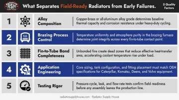
For fleet operators and repair shops sourcing replacement cores, these five factors explain why two radiators built to the "same spec" can perform very differently in the field — and why verifying manufacturing standards before purchase matters as much as verifying fitment.
Common Issues and Misconceptions in Radiator Assembly
Three errors come up repeatedly when buyers, technicians, and procurement teams evaluate radiators — and each one can result in premature failure or inadequate cooling performance.
External appearance doesn't reflect internal quality. Weld seams, fin condition, and overall dimensions tell you almost nothing about brazing integrity or material grade. Two radiators that look identical side by side can have dramatically different joint strength depending on furnace atmosphere control, flux coverage, and alloy selection during manufacturing.
Passing a basic pressure check isn't the same as field-ready performance. A unit that clears minimum testing may still underperform under sustained heavy load if fin bonding is incomplete, coolant channels are partially blocked by flux residue, or tank seals are seated marginally. These failures surface after hours of operation — not at startup.
Dimensional fit doesn't confirm duty-cycle compatibility. A radiator that bolts into the mounting frame may still be under-built for the engine's heat rejection demands. This is especially relevant for high-output construction and mining equipment, where physical fit confirms compatibility but says nothing about whether the core was engineered for the actual load.
That duty-cycle distinction matters at the parts-sourcing level too. For Caterpillar 320/323 excavators, ICEBOX replacement listings include separate SKUs for standard construction versus steel tank/copper-brass core configurations. Material composition is a documented differentiator in those applications — not an incidental detail.
Conclusion
Radiator assembly is a precision manufacturing sequence where quality is built in at every stage — not inspected in at the end. Material selection determines corrosion resistance and fatigue life. Core geometry, brazing control, and tank attachment method collectively govern thermal output and pressure integrity. Testing protocols confirm whether all of that was actually executed before the unit shipped.
For heavy equipment operators and fleet managers, this understanding provides a practical framework for evaluating replacement options. Dimensional compatibility is necessary but not sufficient. When sourcing aftermarket units, ask suppliers to confirm:
- Assembly standards and core construction method
- Tank material and attachment process (mechanical crimp vs. welded)
- Pressure testing protocols and pass/fail thresholds
Radiator Supply House stocks 4,800+ SKUs across 300+ heavy equipment and commercial vehicle manufacturers — including Caterpillar, Komatsu, John Deere, Freightliner, and Kenworth. Both OEM-equivalent and ICEBOX-branded replacement options are available for most applications. For application-specific guidance on replacement specifications and assembly standards, call +1 877-615-3002.
Frequently Asked Questions
How are radiators put together?
Radiators are assembled by stacking aluminium tubes and fins into a core matrix, then brazing the assembly in a controlled nitrogen-atmosphere furnace to permanently bond all contact points. After brazing, header tanks are attached and sealed with gaskets, and the finished unit is pressure-tested before shipping.
What is the life expectancy of a radiator assembly?
No universal service life figure applies across all applications — lifespan depends on assembly quality, operating environment, vibration exposure, and coolant maintenance. Caterpillar's coolant maintenance documentation references intervals up to 20,000 hours, which reflects coolant management schedules rather than a radiator replacement interval.
How much does it cost to install a radiator?
Labor costs vary by vehicle type, regional shop rates, and access complexity. For medium and heavy-duty commercial vehicles, published estimates range from a few hundred to over a thousand dollars in labor. Heavy equipment installations tend to run higher given the disassembly and access requirements involved.
What materials are used in radiator assembly?
Modern heavy-duty radiators primarily use aluminium alloy tubes and fins joined with aluminium-silicon brazing alloy, with tanks made from welded aluminium (preferred for heavy equipment) or reinforced plastic (common in on-highway commercial vehicles). Rubber gaskets seal the tank-to-core joint. Some applications use copper-brass core construction, particularly in certain excavator, truck, and bus configurations.
What is the difference between OEM and aftermarket radiator assembly quality?
OEM radiators are built to the original manufacturer's exact specifications, while aftermarket quality varies widely. OEM-equivalent units match the same material grades, brazing standards, and dimensional specifications; low-cost alternatives may use inferior alloys, skip atmosphere control during brazing, or bypass thorough leak testing. The difference is rarely visible externally — it shows up under sustained operating load.
How do you know if a radiator has been properly assembled?
Indicators of proper assembly include documented pressure test results, the leak detection method used (helium tracer-gas testing provides far greater sensitivity than basic bubble testing), visible weld and crimp quality on tank joints, and OEM part number cross-referencing. Reputable suppliers can provide quality credentials and assembly specifications upon request — if a supplier can't answer those questions, that itself is informative.